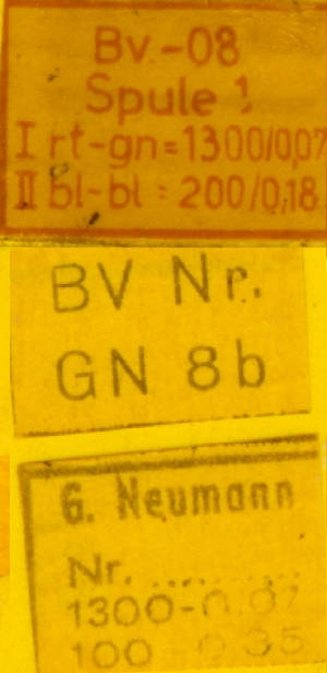
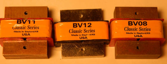
The BVO8 Microphone Output Transformer
First up lets start with some technical specs of the BV8:
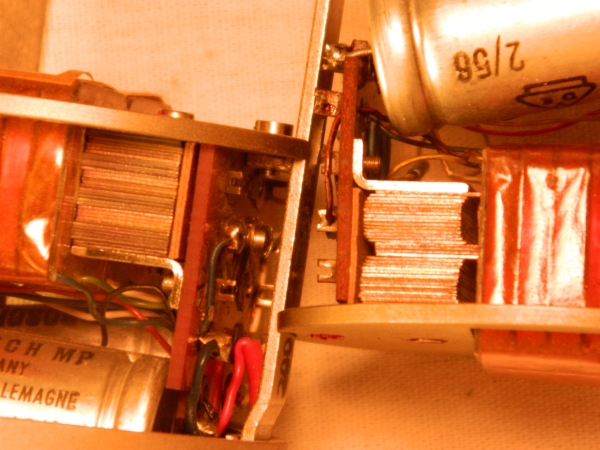
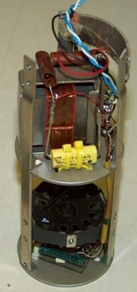
If we just focus on the electrical application, it is nothing more than a capacitor coupled transformer with balanced output.Technical specs are quite amazing, 40 to 20kHz +/-0.5 dB at 0dB (0.775V) at 2kOhm load and a 6.5 to 1 ratio with 2600 to 400 turns and a given output impedance of 200 Ohms (switchable to 50 Ohm via a screw terminal inside the mic).One of the interesting facts of the BV8 is that it has a built-in roll off. By enlarging the value of the coupling caps, the low end actually gets less and not more. How is that done? The four chambers of the BV8 (more about that later down this page) are not wound equally; the two outer chambers have fewer turns than the inner two. Other than standard transformers the BV8 uses block stuffing of the core, meaning we have a five and five lamination pattern instead of the normal one and one pattern. The core build-up works in conjunction with the four chambers to roll off everything below approximately 40 Hz. Just by restacking the core the low end can be improved, but careful, it can get quite mushy, too!Nearly all 47s that came from radio stations have a 1/3 stacking pattern, reducing the low end all the way up to 120Hz with about 10 to 12dB an octave, for studio use a re-stacking of those TRANSFORMERS is a must!
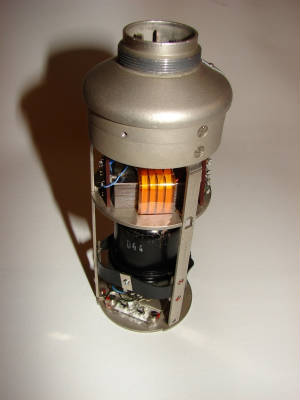
The BV8 is probably one of the best known audio transformers, gaining more and more popularity in recent years. Just by being the stock transformer of the U47 it is special, but it is also one of the few, and one of the earliest, transformers that was developed and designed just for audio.
That might sound a little bit over the top because all audio transformers should be specially designed for audio operations, but nearly all other audio transformers use core material that was designed for power transformers, which spells out in lower production cost. The difference of the UI30 is the lamination size and shape which was specially developed just for audio! Backing up a bit, nearly all transformer lamination are made from at least two parts of ferrous metal that are butt joined, stuffed and stacked together to make up a metal core. Stamping out metal from a flat sheet is just like cutting cookies out of dough but if you make a mistake, you can re-roll dough; for transformer lamination, it spells out scrap. Very early in transformer history the lamination shapes were designed to have little or no cut-offs. This means that the majority of lamination was actually designed to have no scrap. For power transformation it nearly does not matter, but for audio it is quite a different story.
But let's get back to the BV8. In German BV stands for “Bau-Vorschrift”, meaning nothing other then plain "Build up Instruction", the number is mostly just given by the engineer and eight was the magic number.This is not 100% true, because what we call BV8 is actually just the short form of BV-00-08-00.And to be correct in every aspect, there are several versions of this particular transformer, and even stranger, the BV8 was not the first transformer for the U47!
It was a retrofit that saw first action in a U47 sometime around the winter of 1951-1952. It is not clear what transformer was used when the U47 was developed. There are several different transformers that can be found in the very early U47. Some were of Telefunken origin, some of pre-war CMV3 origin, and both were not the best choice for the U47 at all. None of them sounded particularly good.
The now familiar look and sound of the transformer came with a DIN UI 30 retrofit transformer; it was a development of the Zentraltechnik of the NWDR in conjunction with Krupp Stahl, at the time the largest European manufacturer of transformer lamination. In the time frame 1948 to 1951, the two worked closely together to find the best possible shape to side ratio of lamination with reference to frequency response, distortion and overall volume. Aside from the large M shapes that were developed for audio output transformers and the medium size version that can be found in the V4x and V7x pre and post amplifier, the UI 30 was the shape best suited for low level signals such as microphone outputs and preamplifier inputs.
What makes the UI 30 special is the side ratio 1 to 1.16 (30/35mm). The slightly off 1 number is needed to get a frequency symmetrical window of 1 to 1.5, where nearly all frequencies are flowing at the same flux rate. The first lamination did not have any mounting holes (you can find those lamination in early U47s with stand-up transformers), but that proved too difficult in the long run. So shortly after the introduction of the "no hole", two more versions of the UI 30 lamination were introduced: one was the four hole, with asymmetrical hole placing (with reference to the magnetic center); the other was the two hole type with symmetrical placing. Also an LL version of the UI 30 was developed, and those lamination can be found in very early M49 microphones as well as in the microphone inputs of Hiller, Maihak and EAB mic preamplifiers. The M49 was the first microphone that used the UI 30 lamination, developed and tested from 1950 to 1952. 1952 was also the year when it was officially became the new broadcast microphone, replacing all CMV3 mics.
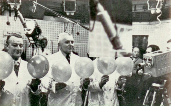
The U47 was introduced in 1949, but was not accepted by the NWDR as a broadcast mic. With the start of the TV studios of the NWDR in Berlin Tempelhof in the Ringbahnstrasse in early/mid 1951, a better microphone than the CMV3 was needed. It was nearly impossible to get clean audio because of the large magnetic HF interference present inside a TV-studio. New microphones were needed quickly, and the decision was made to retrofit Neumann’s newly introduced U47 with the UI 30 core. One other aspect of the UI shape is its high rejection of hum and noise, similar to a Humbucking Guitar pick up. The noise rejection of the new transformer worked so well that Neumann used it for the standard production.
The very early UI 30 style transformer introduced in the winter of ‘51 had a ratio of 8 to 1 and was, like the earlier Neumann CMV transformer, mantle wound. This means that the copper is wound in a continual layer, starting from right to left and back, beginning to end, and primary then secondary. The secondary winding sits like a mantle over the primary. At the same time, the audio lab of Zentraltechnik tried several new winding techniques, some of them going back to the beginning of transformers. Historical magnet wire was not enamel coated like today's. Since around 1940, PVC and Nitro type coatings were developed, but before that, magnet wire was either paper coated or wrapped with silk (Reusen style). The isolation resistance was pretty low, even though bathed after winding in a varnish or wax…in the range of just a few volts. So, transformers were wound as disks and daisy chained with mica wafer in-between, to increase the insulation - a time and work intensive way to improve the volts-per-layer ratio.
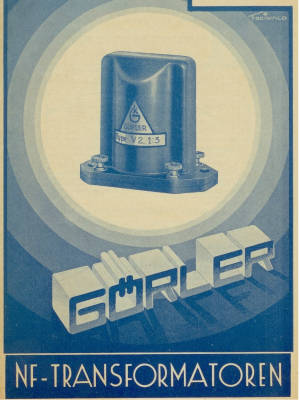
With the introduction of the PVC coating, the easier left right winding style could be implemented…but it also changed the audio response. Then the Zentraltechnik developed a new winding style that incorporated both ways: the disk and mantle way, first used in the output transformer of the M49. Instead of winding separate coils (like in the V4x/7x input transformer) a bobbin was developed with four chambers, so the primary could be wound in four sections and then the secondary winding could be wound on the top of that. The new bobbin was made by the Goerler Company in Berlin, one of the leading transformer manufacturers in Germany. This new style, called section transformers, combined the ease of left right winding with the benefit of the disk type. When Neumann received the production license for manufacturing the M49 in late 1952, they also took the newly developed technology of section winding and incorporated it into the U47 output transformer, turning it into what we now call the BV8.
From 1951 until the end of production of the U47 in the early 60’s, the BV8 came in several different versions. It appears that Neumann equipped the U47 with different transformers for different customers/distributors. All U47’s sold via the original Telefunken company used only the standard 6.5 to 1 ratio with an output impedance of 200/50 Ohm, no matter if it was an early 1952 version sold via Elite Audio in the USA, or a 1962-delivered short body to Venezuela. The U47s sold later in the USA via Gotham Audio first used the standard BV8 200/50 Ohm, but around 1958 switched those Export models with a BV8 looking, but technically different transformer labeled GN8, and later a GN8B version. The original Neumann BV8 production manuals specify three main types with two separate revisions, the 200/50, the 50/12 and the 600/200 Ohm version. The GN data sheets from that time seem to be lost, but after repairing about 100 BV type transformers in the last 15 years, we can tell the winding style and ratio varied from type to type.
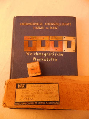
The original Krupp steel, as well as the Vacuum Schmelze, used a Mu-Metal similar type of alloy. But some of the GN type transformers had a 49% Ni/Fe alloy that was also reflected by the turn counts. They were still a 6.5 to 1 ratio, but compared to the standard 2600 to 400 winding count, those transformers had a 4100 to 630 set up. It is quite difficult to re-trace the reason for the slightly different versions over the production time, but it appears that different markets required different technical set-ups. With the end of the U47, and later U48 production runs, the UI 30 lamination shape was still used for the M49 until the end of production during the mid 1970’s. The follow-up mics of the 47, the U67, used the same lamination but with a different winding style. The core height was also changed; the UI 30 was used a final time for the U47Fet. At the beginning of the 1970’s, transformers started to fall out of favor; Krupp steel stopped the UI 30 production in 1973 and the Vacuum Schmelze ran the last production run in 1980. UI 30 lamination was still offered by different smaller companies but none of these lamination were of the same quality as the original A50 grade.
The Neumann BV Type Transformers Today
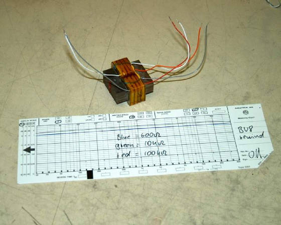
Neumann was the only company that made the historic BV8 transformers. All production was done in house at the Berlin factory location, including the BV08 for the U47/48, BV11 for the M49, and BV12 for the U67/M269. With an average age of 50 years or older you should be happy if your BV transformer still works fine. To keep it that way, do not try to move wires or do DC base measurements! The best and safest way is not to touch it! The Polystyrol bobbin is fragile and breaks easily. Most broken transformers that where sent here for rewinding were damaged mainly because of wrong handling. AMI Inc. became involved in re-making BV type transformer in the late 90’s, after several U47s showed up at our repair place in Seattle with missing transformers. Those U47s with modern replacements never sounded the same, like a good car that is missing the original engine does not handle the same. After a lot of research and buying up a bunch of NOS lamination from the original suppliers in Germany, we started to remake the BV8 in small quantities. The Neumann company was very helpful, and provided us with all documentation that they had left of the BV types; some old Telefunken engineers as well as some retired engineers of the former NWDR helped us out with nearly all documentation of NWDR made BV transformers.
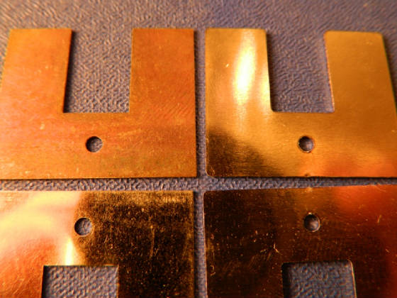
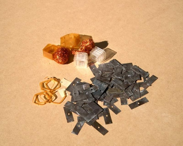
Some of our tests on in house made lamination (Today's cutting is getting easy with lasers/water-jets)
The bobbin situation was quite difficult, as well as getting identical magnet wire. We started from a few transformers to a monthly production and within a year we had several OEM customers that used our BV8 for their Neumann repair and recreation of new mics. The first BV8 transformer we made was tested by Gunter Wager of Wagner microphones and a short time later by David Bock; both of them still use our transformers today. Not too long after, it got difficult to get the required NOS lamination so we started to make a replica of the UI 30 lamination here in the US. From 2001 to today, we sold over 10,000 BV transformers in several different versions. About two years ago the situation of the NOS lamination got pretty bad and we began to go new ways for recreating the UI 30. Our generic BV replacement transformer uses the original Krupp Steel footprint with 4 holes, but for historically correct repairs, we need the proper look. It can be quite difficult to get there, as our production numbers in one year are about what Krupp stamped out in a day 50 years ago. It took us quite some detours and tries to get somewhere close to the original specs. We tried everything from laser cutting to water jetting and even when the results were quite useful, the price to get there was way too high. Earlier this year, we found a new way to get 100% identical lamination that we can offer now for just a small difference in price to our generic version of the BV types.
We are proud to announce our Classic BV type series of transformers, not only do they sound and feel the same as our generic versions, but they actually look like they were made in Berlin in the old days.
Also Read:

