TLM49 Conversion Metalwork
The most challenging aspect of this remodeling project is the metalwork. If you have no experience with turning and cutting metal on a lathe...
STOP!!
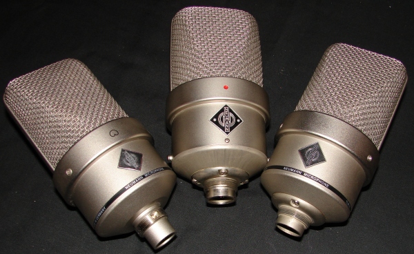
The TLM49 metal housing is not built identically to the historic M49. It has extra metal on the housing to provide places to secure the new high-tech style buffer amplifier that is made for this unit. The TLM, which stands for Transformer Less Microphone, also does not have enough room for the appropriate BV11 transformer needed for coupling to either tube that you select for use in this remodel.
The unit needs to be opened up in order to have enough space for the transformer and tube. If you do not have a way to turn down the metal housing yourself you will need to find someone who can do this for you. Before proceeding with any other section of the remodel, you should find a solution for proper turning on the metal housing.
If you are experienced with metal work and have access to a good metal lathe, proceed to the section below!
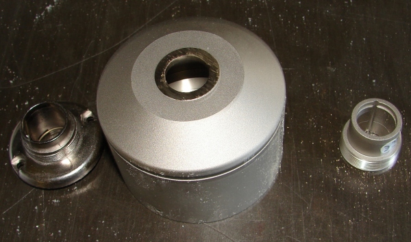
The first step is to take the your TLM49 completely apart. Remove the head basket. Decouple the XLR connector from the internal amplifier. Gently pull out the inner structure with the components and set it aside in a safe and dust free location. You do not want any dust or debris to come in contact with the capsule, especially if you plan to use the current capsule in your remodel. At this point you should have the bottom bell as shown in the picture below.
The stock connector of the TLM49 can be utilized via a 7-pin XLR which would save a bunch of metal work and money, but it creates some long term problems. Its design it is not as rigid as the original IRT specified 7-pin connector. If you decide to go with the sturdier connector, the XLR needs to be cut off and the hole turned down to make room for the Tuchel type connector. You can find this connector through Binder, part number 09 0043 00 07. Binder also makes available the technical drawing with all of the measurements for this part. This way you don't have to question whether your own caliper measurements of the connector are accurate.
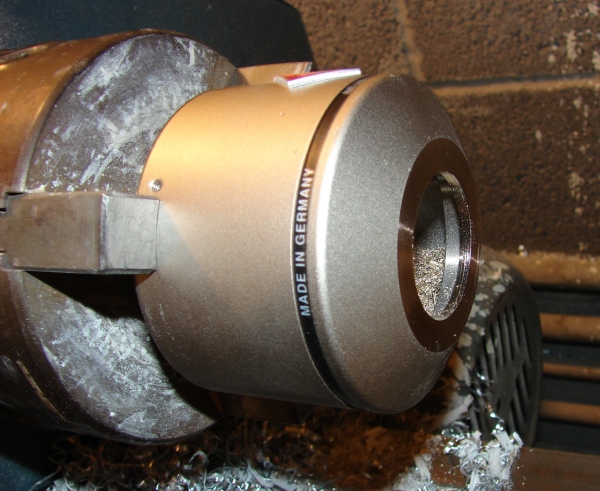
The center hole on the bottom bell needs to be enlarged to properly incorporate the Binder/Tuchel insert holder shown on the left. Always remember to measure twice and cut once. An experienced metal worker can turn down the end bell in about 30 min. If done properly, the final job won't show any visible brass when the insert holder is attached. When properly cut, it will look like the picture below:
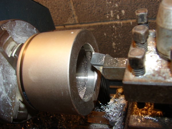
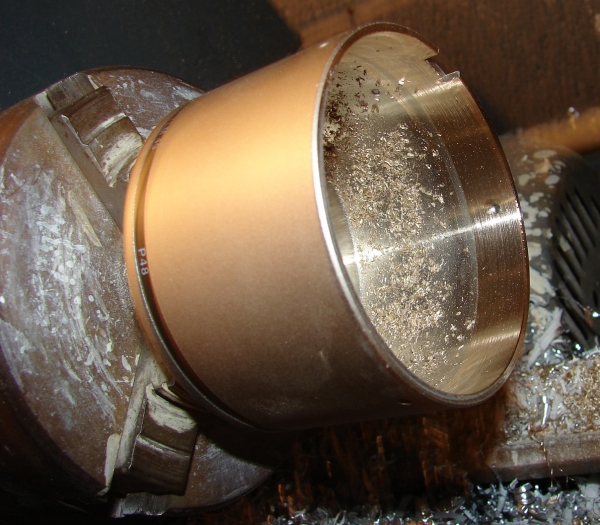
Next, you need to flip the bottom bell around to turn down the other side. On the inside of the housing, there is a metal lip that holds in the high-tech ceramic wafer containing the emulation circuit. This needs to be removed so that the vintage syle electronics have enough room to slide into the housing properly.
Make sure that you do not dig into the side walls at all. It is important to ensure that the turn winds up flush all the way through the bell as it is shown in the picture below
At this point, the metalwork is finished. It's not a lot of work but it is specialized and tricky and with one slip you can find yourself shopping for a new microphone! It's important to take your time doing this work and to measure twice and cut once.
Also Read:

