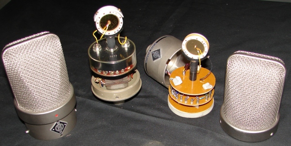
TLM49 Conversion Electronics
The TLM49 is a romantic attempt to emulate Neumann's past greatness in the form of an IC based sound emulator instead of using a tube and transformer. While the microphone is a solid microphone for the studio, the IC emulator does not compare to the original electronics used in the historic M49. While going transformerless may make the circuit more consistent from microphone to microphone (and cheaper...) the modern versions are missing the warmth and character that the AC701 tube and the BV11 transformer imparted on the sound of the M49. Due to these two components, the real or home made M49 produces dynamic harmonics that interact with the room and singer whereas the TLM49 emulator is triggered by level markers that produce static harmonics at each level that will always behave the same every time that they are triggered. The difference between analog and digital!
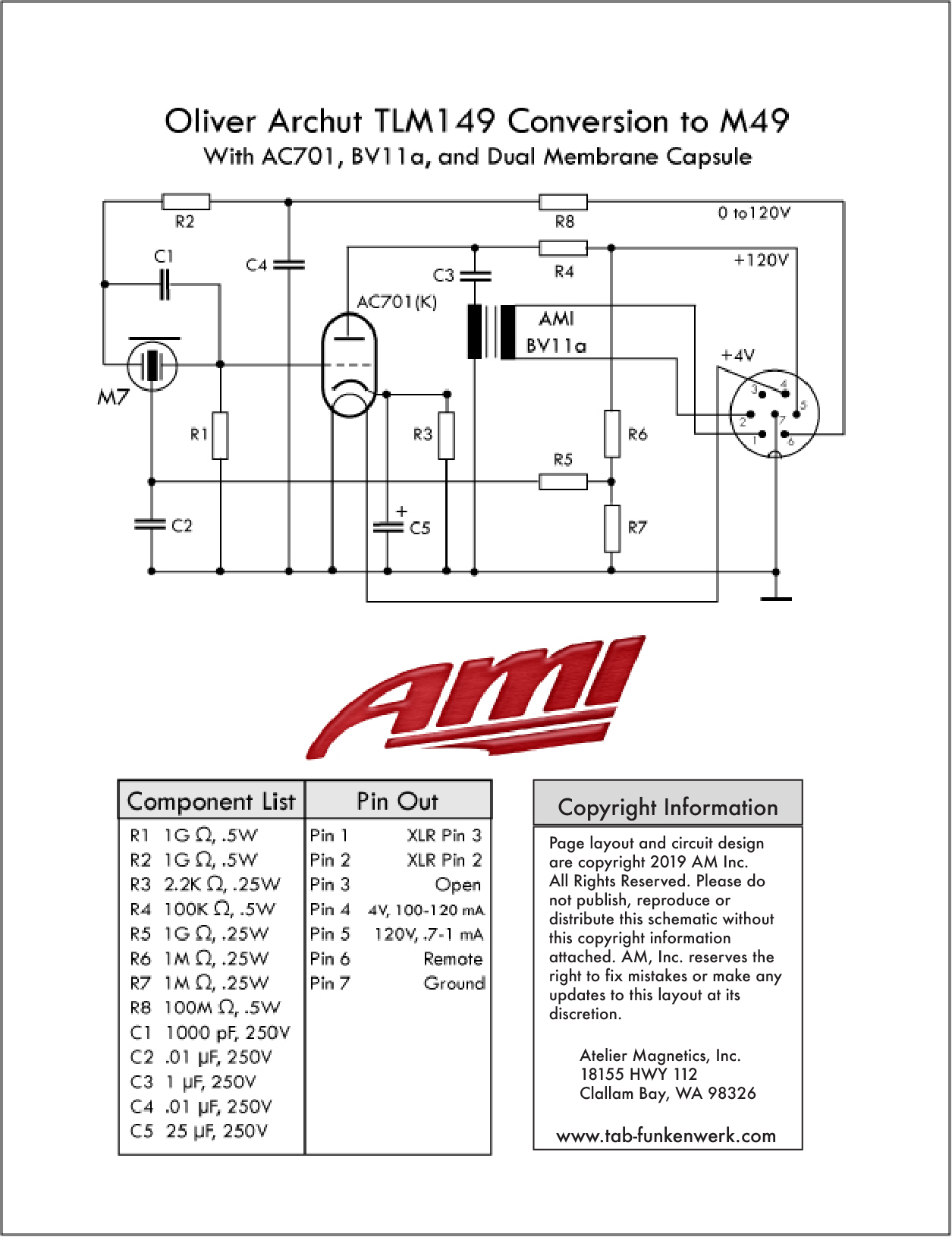
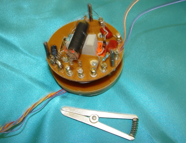
When doing the final assembly of the electronics into the inner structure you should start from the bottom up. The bottom plate holds the transformer in place and once this is secure you can add the next plate up. Once that is firmly in place it is time to mount the tube. Both the AC701 and the EF732/5840 tubes are miniature tubes that need to be hard wired to their connections. The tube needs to be shock mounted with some sort of insulating neoprene foam that can withstand a couple hundred degrees Fahrenheit. We use Thermax which comes with an adhesive backing. If you use some other type, we recommend using E6000 epoxy to hold it in place. E6000 is great not only because it is very secure (almost permanent) but when you do want to take it off, it will rub off the surface with a little work as if it had never been there. It also has a high impedance.
Note in the picture that each lead from the tube has been coiled. You can simply crimp them as well. If you leave them straight, the leads can act like strings and vibrate due to motion or loud signal in the room causing noise in the tube during recording! We also recommend while soldering the lead in wires that you use a small aluminum heat sink to help protect the glass on the tube.
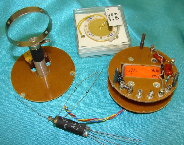
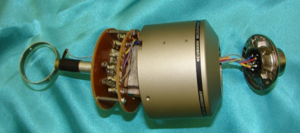
Once every other component has been installed, properly connected and you've determined that the structure will fit inside the housing, it's time to test the voltages. Hook the inner structure up to the power supply to make sure that all of the voltages are within the spec. Once you have determined that the voltages are correct, it is safe to install the capusle! The capsule assembly is shockmounted on a donut shaped piece of Thermax. The first of the historic M49 microphones came with M7 capsules installed. Later versions came equipped with K49 capsules. For your build, if you wish to create a version with remote polarity switching, you will need to purchase either an M7 or K49 as both have front and back diaphragms. You can try to find new old stock versions (NOS) but we believe that the Thiersch M7's are a great option in a new capsule. On the K49, we highly recommend the Sennheiser version, part number 053291. Make sure that you have the appropriate capsule holder for the capsule that you purchase!
In this picture I used an original K49 capsule holder that was enlarged with a handmade aluminum spacer because the stock TLM49 electronics were migrated into a new mic housing to use as a different microphone. The owner wanted this TBM49 to be an all pattern mic like the historic M49 and unfortunately the TLM49 comes with a quasi K49 that is only sputtered on one side making it cardioid only. In this rebuild we used the Sennheiser capsule mentioned in the previous paragraph.
Aside from the use of a standard 3-pin XLR instead of the historic Tuchel connector and a few different construction features, the mic is very similar to an original M49. The original Tuchel connecter went obsolete about 15 years ago, but the connector of the 7-pin HF proof version of the M249 is still made by Tuchel as well as by Binder. The Binder part number for the 7 pin M249 type connector is Part # 09 0043 00 07 and you can buy it via http://www.binder-usa.com/.
The mechanical layout is nearly identical to the original NWDR layout so that the chance for cross coupling electric fields that trigger any form of noise or buzz is minimized. The end result is an electronic and mechanical mark up of the M49 that is virtually identical in sound and response to a good working specimen. Please note that in over 20 years production Neumann changed the electronics several times. With over 6 entirely different x-former winding styles and ratios and 3 revisions of the electronics it is quite hard to pinpoint what the "Official Sound" of an M49 should be. But I have built several different versions (standard/B and C) that if matched up with their historic counterparts sound identical. I also did a variation that Neumann never did; the early NWDR transformer with AC701K and C circuit, that can focus the M49 sound in ways the original designers never could dream about. I hope you had fun reading this article!
Also Read:

