TLM49 Conversion Inner Structure
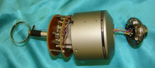
With the metalwork complete, it's time to start work on the inner structural components for your remodel. Remember that the inner structure that came with the microphone was not designed to hold a large transformer like the BV11 nor was it properly sized to accommodate a vacuum tube. While building the new inner structure is a little tricky, it is not nearly as specialized as the metalwork. If you have experience with a drill and a Dremel tool and you have some patience, you should be able to work your way through the next section without too much difficulty. Plus, if you mess up, you just need to reprint a label and re-cut some hard paper board (or epoxy board), neither of which is very expensive.
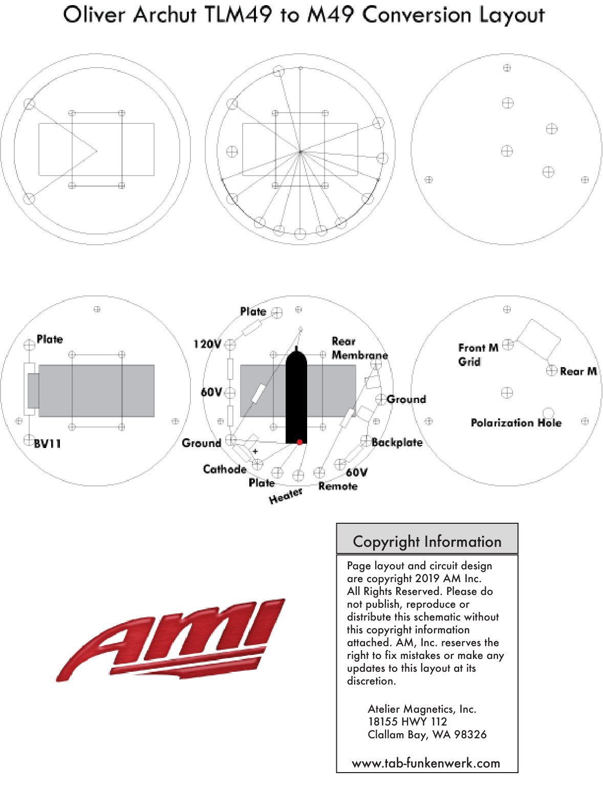
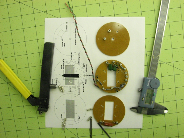
To get started on this portion, first print out the PDF file (the JPEG is below for quick reference) and make sure that the diameter of the circle is 63mm. Once you have the size correct, print it out on an Avery 5165 or similar full label sheets.
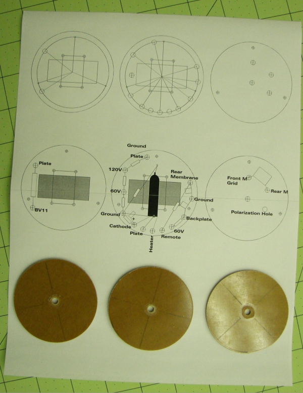
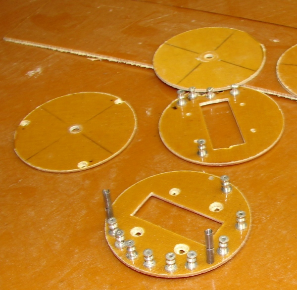
Buy some sheets of hard paper or epoxy board. You are looking for something that is about 3mm thick, has a high impedance and a good mechanical strength to it. Cut out three or more disks all with a diameter of 63mm. Cut them close to diameter (a little wider) on a band saw and trimmed them on a lathe to get them perfectly circular. They will look something like the discs shown in the picture below
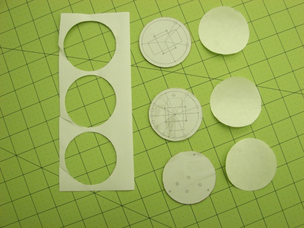
Now double check and make sure that the label you previously printed out fits the actual size of the board discs that you now have. Once you have a label where the print size matches the board discs, cut out the label stock and apply them to the disks. This will become your template for drilling and cutting the deck plates of the inner structure.
Next, drill the proper size for the stand offs that you have chosen. I use Keystone double layer standoffs. There are several press in types that will work, like Keystone 1514-2 or the 1510-2, etc. Whichever standoffs you choose, make sure that they can accommodate Teflon sleeved, multi-stranded 28 gage or 30AWG wire.
For the transformer cut outs a Klein Tool Part# 76011B will do a terrific job! But a Dremel with a cut off wheel will work just as well with a little more difficulty. Note that the first deck has a notch that needs to be cut out on the side where the capacitor will reside. This is to allow the wires from the Binder connector to slide through to the second plate. When you have finished drilling the holes and cutting out the transformer slots, peel the stickers off all of the discs and wash the boards down with acetone. You can now start adding the standoffs and then the components to each deck.
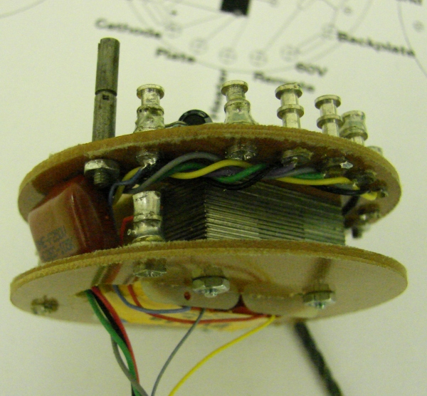
For the transformer assembly I used 2-56 by 3/4 non-magnetic stainless steel bolts. The spacers for in-between the 2nd and 3rd deck are 2-56 by 1/4, two stacked to get the needed clearance, but a 1/2 inch spacer will also work.
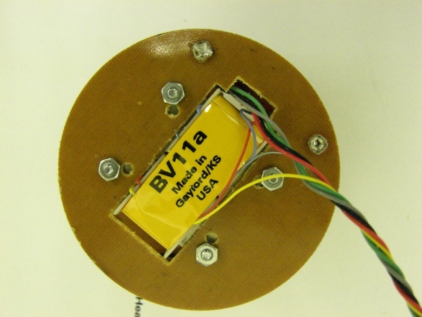
Note on the 1st deck the extra cut out on the one side to accommodate the lead-in wires that go to the Binder connector.
Also Read:

